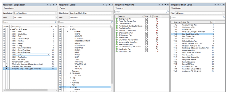
There are some common repetitive tasks that we do when we start a new Architecture project in Vectorworks. In this article I will show how these can be speeded up by utilizing micro-automation created in the Marionette AAD tool. I will show these three steps: creating Classes, Creating Design Layers and Creating Sheet Layers with Viewports on them. I will include at the bottom a link to the Marionette scripts I have used to accomplish these tasks.
Marionette is a built in Visual Programming language in Vectorworks. It has limited functionality in comparison with similar but more extensive tools such as DynamoBIM or Grassshopper3D. However, because it more integrated into the host software it has a couple of really nice features to be able to create Marionette Menu commands from scripts and Parametric symbols that can be edited from the Vectorworks User Interface without the need to edit script.
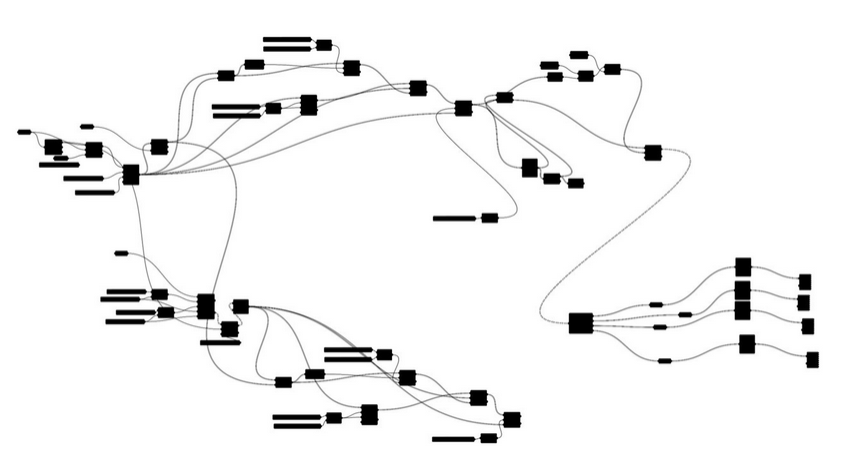
Below is a generic image of Visual Programming scripts composed of boxes and wires. The boxes are called nodes and the wires are connections passing data from one node to the next. Marionette scripts look similar to this.
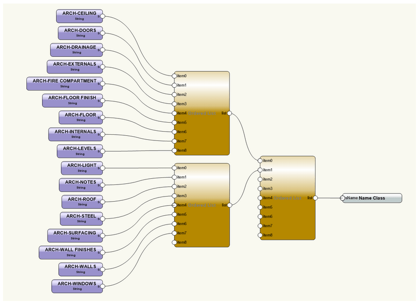
In this first script I only need a few nodes to automatically create a collection of new classes in the base document. The key node performing the action is the grey node on the right hand side.
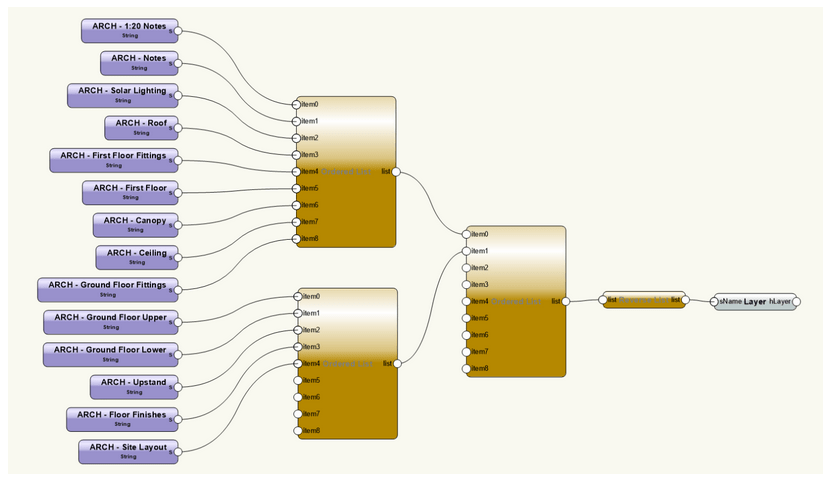
The next step is the create the design layers. Again, the key node is the one on the right hand side.
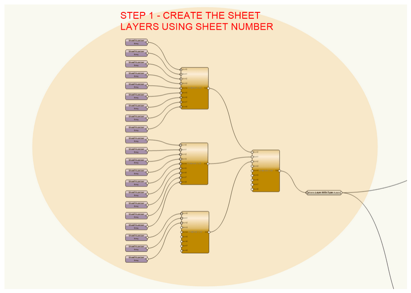
Finally, we can create a series of sheet layers and generate plan viewports to put on them. Below is the full script, it can be divided up into 7 different parts. Each of the seven parts of the script does a different job.
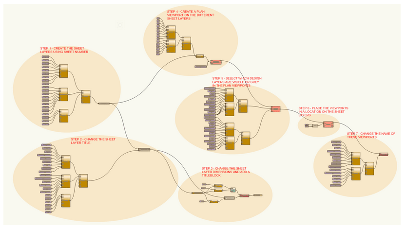
Step 1 – The key node here is the grey node ‘Layer With Type’ which creates Design or Sheet layers when given a string for the number of the sheet layer.
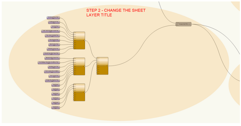
Step 2 – This step changes the Sheet Layer Title. The key node is the grey node ‘Change Sheet Title’.
Step 3 – This step changes the dimensions of the sheet layers that have been created and adds a title-block to the sheet layer.

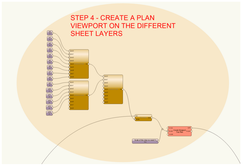
Step 4 – This step creates the Viewports, the key node is the red node ‘Create Viewport Top Plan’. It can only generate Top Plan Viewports. You need to feed it a design layer and a scale factor.
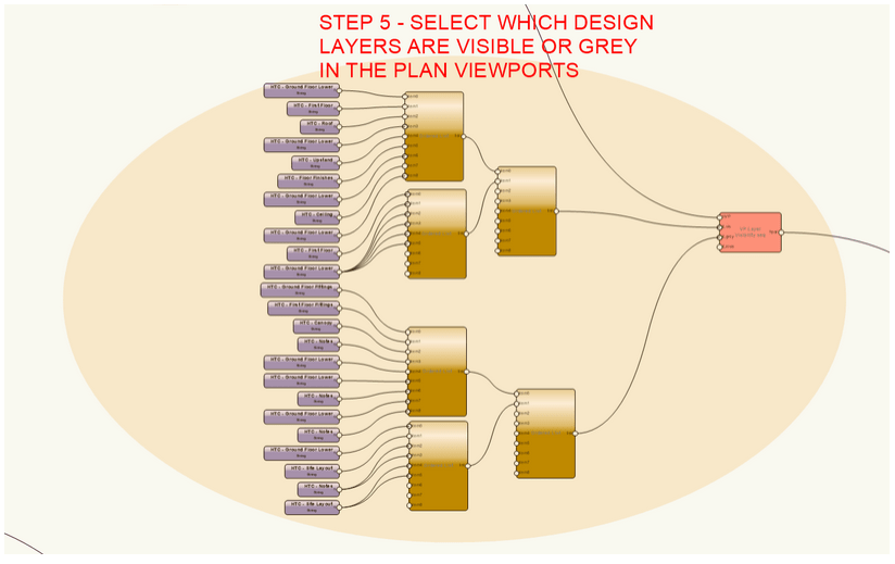
Step 5 – This step is setting up the Viewports, so the correct design layers are visible, and which are set to ‘grey’. The key node is the red node ‘VP Layer Visibility seq’.
Step 6 – This step places the viewports on the correct sheet layers using the ‘PutByRefPt’ node.

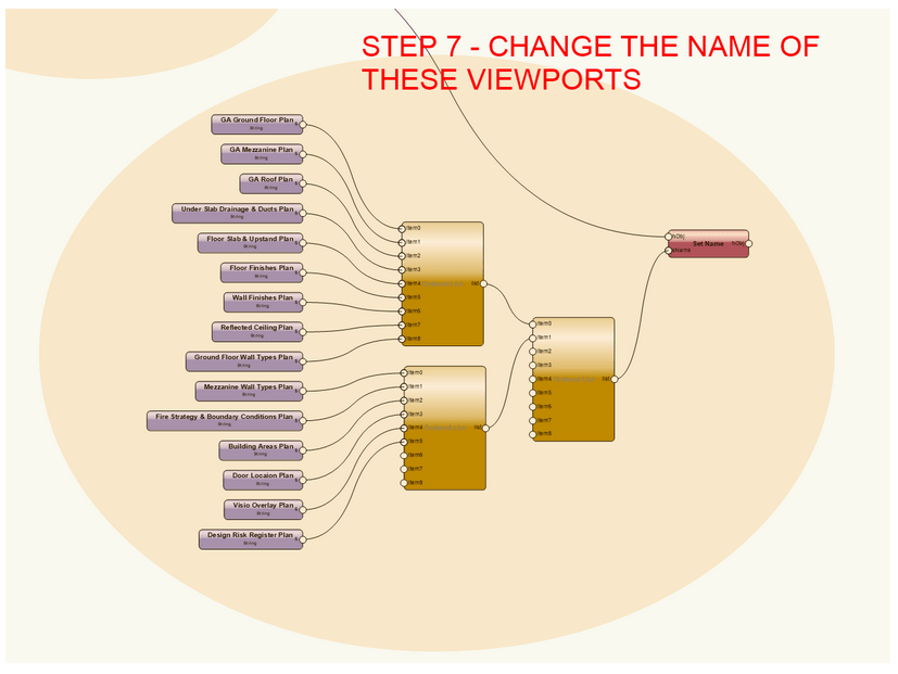
Step 7 – This final step just changes the names of the viewports so they can more easily be found later. It is a bit of housekeeping.
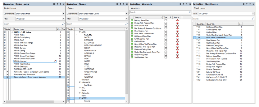
The results of these scripts are that you have quickly and easily create all the needed classes, design layers and sheet layers. It has also generated a few of the plan viewports and placed them on the sheet layers. Below is a link to the Marionette script used in this article. These scripts can be turned into Marionette Menu Commands.
Vectorworks Marionette Files | Powered by Box
#VectorWorks #MarionetteAAD
