We here at GS have been investigating the use of Dynamo for the design stage of projects. In this article I will look at three designs for two projects where Dynamo was used to create the desired geometry.
Project 1 – University Music Room
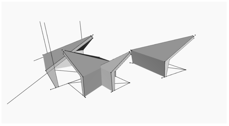
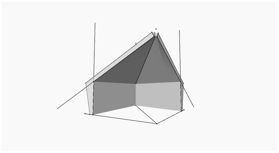
The split mono-pitch roofs of this design were modelled in Dynamo. In an earlier iteration we modelled them as model in place masses. Using model in place masses we were able to get close to what was desired but to achieve a more accurate geometry for the roofs we had to use Dynamo.
To begin with we created three model lines on plan inside Revit. These would form the skeleton for the geometry created inside dynamo.
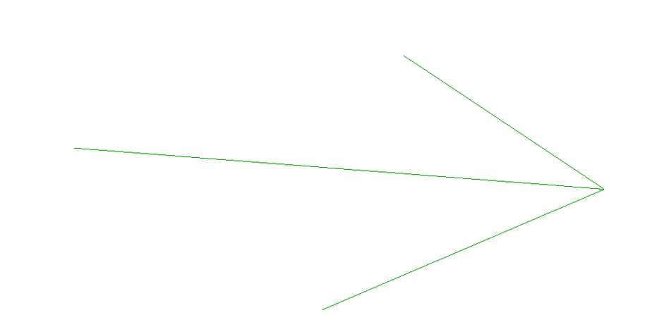
Step 01. Select a model line in Revit and use a plane of this line to be a guide for creating a polycurve inside Dynamo that is the outline of the roof.
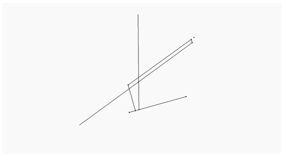
Step 02. Run this same algorithm on three lines from Revit to create three polycurves. These create the three outlines for the roof element.

Step 03. Finally, these three polycurves are lofted to create a solid. Which is imported into Revit as a mass which can be further edited inside Revit.
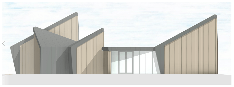
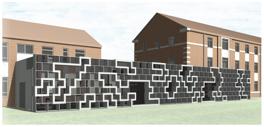
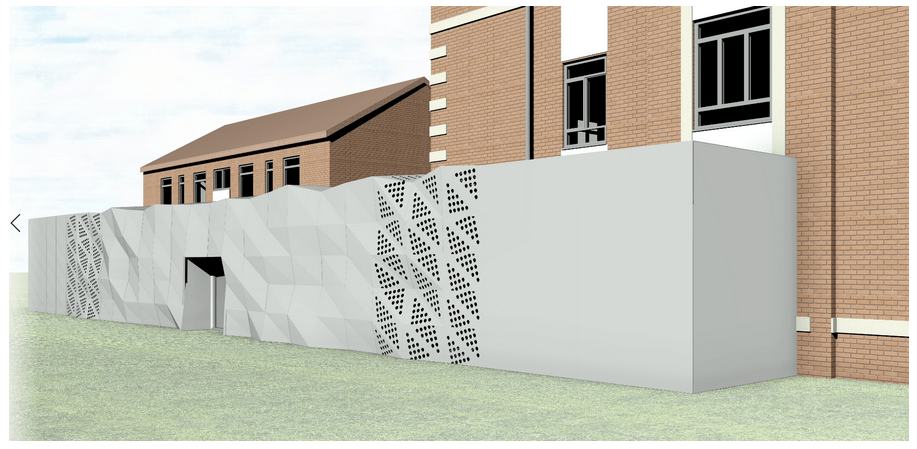
Project 2 – University Link building
This is another example of a project where we used Dynamo during the conceptual design stage. The brief of this project was to create a low-level linking building. The two brick buildings at either side of the images below are existing buildings on the site. The long and low building connecting the two brick buildings is the design proposal.
Step 01. First all I used the Lunchbox package to create a staggered grid of rectangles.
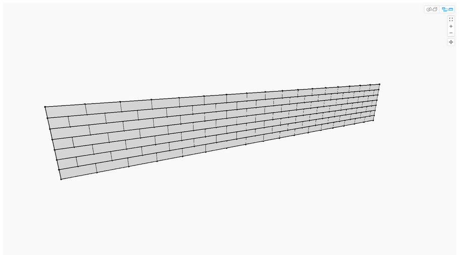
Step 02. I then created a series of random curves and found the intersections between these and the rectangles.
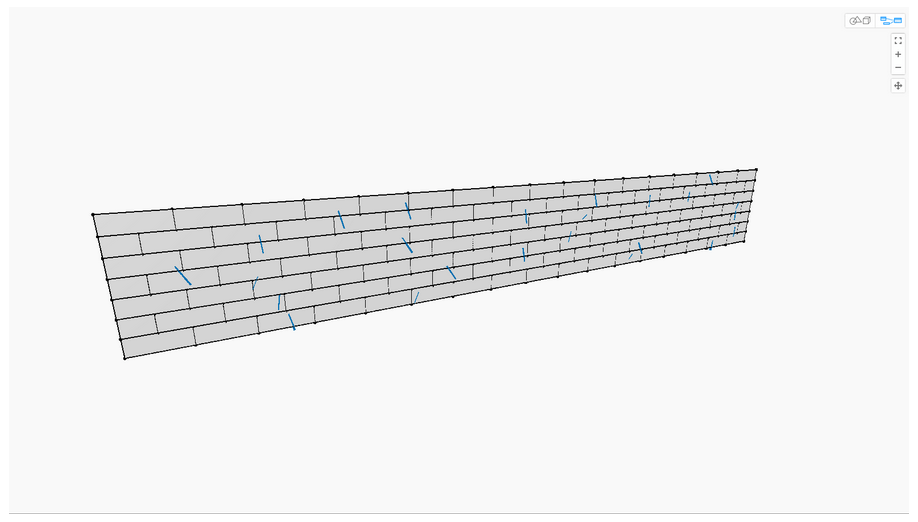
Step 03. This created regions rectangles that intersected the curves. This is what I used to generate the shapes in the Tetras pattern.
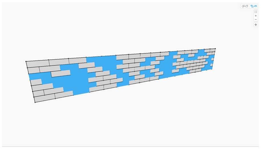
Step 04. In the final step I thicken the outline of the Boolean union groups of rectangles to define the shapes.

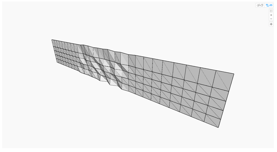
This final design concept was tricky to create in Dynamo because Dynamo doesn’t have a tool for creating triangulated mesh on a plane. I tried with creating a Toposurface mesh but this only worked on a plane orientated in the Z direction. The eventual method I had to use was to create a Nurbs surface and project the triangles onto it.
Step 01. I created a triangulated surface pattern using the Lunchbox plugin.

Step 02. I created a series of vertical Nurbs curves that started off straight and then become wavy in the middle and then straight again at the end.

Step 03. I used these Nurbs curves to loft them to create a Nurbs surface.
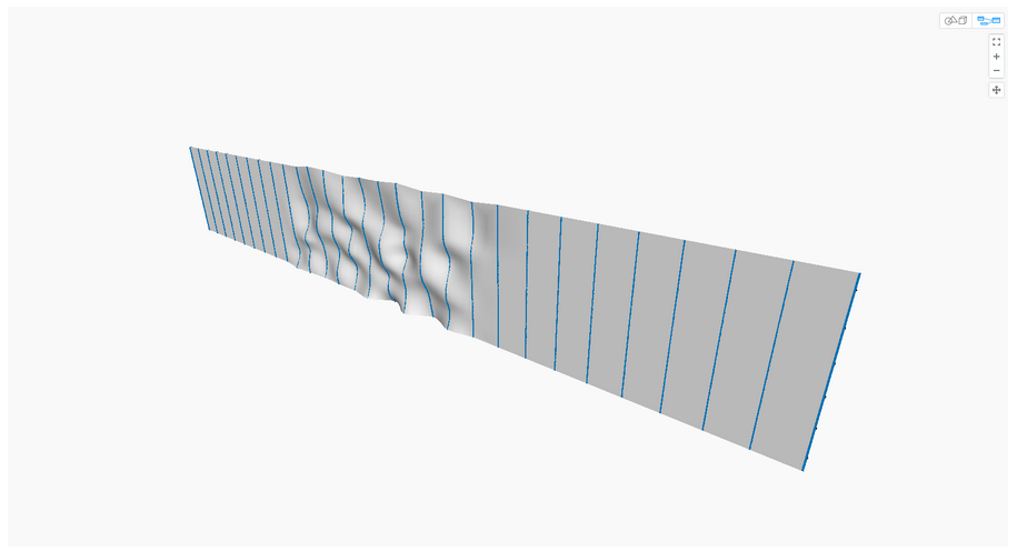
Step 04. I then projected the triangles onto this Nurbs surface.
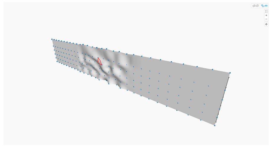
Step 05. In the final step I created the deformed grid of triangles. In the actual script I used 3-point adaptive components to create the elements inside Revit.
#Dynamo #DynamoBIM #Revit #RevitArchitecture #Parametric #Design
